 The Scottish mathematician and lawyer Archibald Smith first published in 1843 his equations for the magnetic deviation of a ship, or in other words, the error in the ship’s compasses from permanent and induced magnetic fields in the iron of the ship itself. This effect had been noticed in mostly wooden ships for centuries, and broad attempts to minimize it were implemented. But the advent of ships with iron hulls and steam engines in the early 1800s created a real crisis. A mathematical formulation of the deviation for all compass courses and locations at sea was needed in order to understand and compensate for it, and Smith became the preeminent expert in this sphere of activity. With Capt. Frederick J. Evans he extended his mathematical treatment to detailed procedures for measuring the magnetic parameters for a ship, and he also invented graphical methods for quickly calculating the magnetic deviation for any ship’s course once these parameters were found, constructions called dynamo-gonio-grams (force-angle diagrams), or dygograms for short.
Today, radio navigational systems such as LORAN and GPS, and inertial navigation systems with ring and fiber-optic gyros, gyrocompasses and the like have reduced the use of a ship’s compass to worst-case scenarios. But this triumph of mathematics and physics over the mysteries of magnetic deviation, entered into at a time when magnetic forces were barely understood and set against the backdrop of hundreds of shipwrecks and thousands of lost lives, is an enriching chapter in the history of science. Part I of this essay presents a brief sketch of the problem and the analysis and solutions that were developed to overcome it. Part II sets out with a discussion of Smith’s graphical methods of computing the magnetic deviation and concludes with a list of the references cited in the essay.
The Sources of Compass Error
Assuming they are constructed well, compasses on ships fail to point to true (geographic) north due to two factors:
- Magnetic variation (or magnetic declination), the angle between magnetic north and true north due to the local direction of the Earth’s magnetic field, and
- Magnetic deviation, the angle between the compass needle and magnetic north due to the presence of iron within the ship itself.
The algebraic sum of the magnetic variation and the magnetic deviation is known as the compass error. It is a very important thing to know.
Magnetic Variation
Magnetic variation has been known from voyages since the early 1400s at least. Certainly Columbus was distressed as he crossed the Atlantic to find that magnetic north and true north (from celestial sightings) drifted significantly, and in fact by 1542 it was known that an agonic line, where no difference between the two exists, runs through the Atlantic.
In 1581 Robert Norman published his conclusion, based on his records of magnetic variation, that the “point of respect” of a compass lies within the Earth rather than, say, a mountain of lodestone in the North as many supposed. This led to Dr. William Gilbert’s construction of spherical lodestones to model the Earth and his proposal that it acts as a giant dipole magnet.
We now know that the locations of the Earth’s magnetic poles are not coincident with the geographic poles—not even close, really—and they are always wandering around. Even then, the Earth’s magnetic field is not a simple dipole, and geological masses can also affect the local magnetic field. Henry Gellibrand discovered in 1635 that there are also secular variations that change in time: slower ones due to changes in the Earth’s magnetic field, and more sudden and temporary ones due to sunspot activity and magnetic storms in the ionosphere.
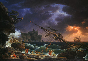
These magnetic variations are important, particularly on long ocean voyages. The mapping of these values led at one time to proposals to use on-board measurements of magnetic variation to determine the longitude of the ship; with sightings taken for the latitude this would provide a ship’s location anywhere in the world. And knowing your location at sea was paramount. When the famous Longitude Prize was announced in England in 1714 (triggered by the loss of 2000 sailors and four ships of the Royal Navy off the Scilly Islands in 1707), the three main contenders for it were measurements of lunar parallax, clock time, and magnetic variation.
 The first ocean voyages dedicated specifically to scientific research were those of Edmund Halley. In 1698 he commanded the ship Paramour, traveling the South Atlantic measuring the latitude, magnetic declination and longitude when possible. (The longitude was found by observing eclipses of the moons of Jupiter to retroactively determine universal time when compared against these events as recorded in England.) Based on this and a subsequent voyage in 1699, Halley published in 1701 the world map below displaying the known magnetic variations (in A new and correct sea chart of the whole world showing the variations of the compass as they were found in the year M.D.CC., by Edmund Halley, found here), information that was later ignored to his peril by Admiral Shovell, the commander of the fleet in the 1707 disaster. The bold line in this map that emerges from the southeastern U.S. and veers southward across the two halves and past West Africa is labeled the The Line of No Variation, the agonic line of his time. His “Curve Lines” of equal magnetic variation (today called isogones) were first used by Christovao Bruno in the 1620s, but this is the earliest surviving example of such a map. It doesn’t seem much of a stretch to me to imagine that this might have influenced Faraday in his concept of magnetic field lines 150 years later. Captain James Cook used a copy of Halley’s map on his voyages around the world.

 As Halley noted, these maps must be regularly updated, and ships studiously logged the differences between their compass heading and true north obtained from astronomical sightings. A map of the world’s magnetic variation in 1800 is shown to the right (from here using US Geological Survey models). You can see that the bold agonic line had moved in that span of 100 years. The variation off the coast of England, as another example, increased to -30° from less than -10°. Ultimately Halley modeled the Earth’s magnetic field as four magnetic poles, two in the crust and two in an interior rotating ball, none with symmetry. It’s a shame that Halley only infrequently measured the dip, or inclination, of the Earth’s magnetic field, thinking it not nearly as important as the horizontal force.
Magnetic Deviation
There is an additional effect on the compass needle that took much longer to appreciate and even longer to understand. This magnetic deviation is due to the iron in a ship, and even the small amount of iron in wooden ships had an impact, although it was often masked by shoddy compass construction. The first notice in print of this effect was by Joao de Castro of Portugal in 1538, in which he identified “the proximity of artillery pieces, anchors and other iron” as the source. As better compass designs appeared, a difference in compass readings with their placement on the same ship became more apparent. Captains John Smith and James Cook warned about iron nails in the compass box or iron in steerage, and on Cook’s second circumnavigation William Wales found that changes in the ship’s course changed their measurements of magnetic variation by as much as 7°.
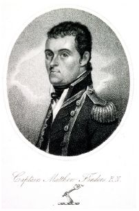 Captain Matthew Flinders (1774-1815) spent years in the very early 1800s on voyages to investigate these effects, discovering that in addition to the horizontal magnetic field of the Earth, the inclination (or dip) of the field contributes to the magnetic deviation as well, or in other words, that both the vertical and horizontal components of the Earth’s magnetic field affect a compass. He eventually discovered that an iron bar placed vertically near the compass helped overcome the magnetic deviation, and this Flinder’s bar is still used today in ships’ binnacles. Dr. William Scoresby later isolated the soft iron in the ship as being magnetized by the Earth’s magnetic field and thereby affecting the compass.
The effects became much more pronounced after 1822 when construction of ships with iron hulls and steam engines commenced. Here it was discovered that hard iron, which becomes magnetic when pounded as during the construction of a ship, turns the ship into a permanent, multi-pole magnet. And this magnet changes slowly under the pounding of waves or vibrations from engines, or suddenly through collisions. George Airy, Royal Astronomer of Greenwich, initiated the procedure of swinging a ship to measure its deviation, and then to correct it with permanent magnets and chains of soft iron in the binnacles, but his corrective actions did not work worldwide, particularly south of the magnetic equator where the dip reversed sign or under the changing conditions mentioned above. Public disputes occurred between Airy and Scoresby over magnetic compensation methods for ships [see Smith, 1869], with a third front opening from those such as F. J. Evans who preferred to simply subtract tabulated values of magnetic deviation at ship locations.
The Mathematical Description of Magnetic Deviation
Beginning in 1843, Archibald Smith (1813-1872), a warm man “behind a reserve which is perhaps incident to engrossing thought” [Thomson], derived and developed his set of equations for magnetic deviation. They are expressed in terms of the ship’s magnetic or compass course, the horizontal component and dip of the Earth’s magnetic field at a given location, and magnetic parameters unique to a given ship. For narrative flow the essence of the derivation can be found in a separate document here (it is the Appendix in the PDF version of this essay). The two principal results are

and
![]()
where the ship’s head is pointing at an angle ξ from magnetic north at a given location (the magnetic course), and at an angle ξ′ as shown on the compass (the compass course). The magnetic deviation δ of the compass needle from magnetic north due to the ship is then ξ – ξ’. The first equation above provides the deviation using exact coefficients A, B, C, D and E but is expressed in terms of the non-observable magnetic course, while the second equation is expressed in terms of the observable compass course but uses inexact coefficients A, B, C, D and E. Therefore, the second (inexact) equation is most useful on-ship, while the first (exact) one is more useful in characterizing the ship. The relationships of the terms in the second equation to those in the first are:

where at a given location of the ship,

and A, D, E, λ, c, P, f and Q are parameters deduced for a particular ship.
This set of equations takes into account the magnetic effects of both hard and soft iron in the ship. Hard iron possesses permanent magnetism, while external magnetic fields such as the Earth’s induce magnetism in soft iron. In essence magnetic deviation has the following components:
- A constant term A due to any misalignment of compass north to the ship’s keel line and to asymmetrical arrangements of soft iron horizontally in the ship.
- Semicircular forces (those with a period equal to 360°):
- Fore and aft components of the permanent magnetic field due to hard iron and the induced magnetism in asymmetrical vertical iron forward or aft of the compass–the B sin(ξ′)term.
- Athwartship component of the permanent magnetic field due to hard iron and the induced magnetism in asymmetrical vertical iron port or starboard of the compass–the C cos(ξ′) term.
- Quadrantal forces (those with a period equal to 180°):
- Induced magnetism in symmetrical arrangements of horizontal soft iron–the D sin(2ξ′) term.
- Induced magnetism in asymmetrical arrangements of horizontal soft iron–the E cos(2ξ′) term.
 The terms P/H in B and Q/H in C are due to the permanent magnetism of the ship. The magnetic forces P and Q are not dependent on H, but the reciprocal of H appears because the countering force tending to keep the needle on magnetic north is given by H.
Even though the quadrantal terms D sin(2ξ′) and E cos(2ξ′) are dependent on the induced magnetism in the soft iron, it turns out that they are not dependent on location. This is because the quadrantal force is proportional to H, and the force that keeps the needle on magnetic north is H, so as H changes the two forces vary in the same proportion and the net deflection is constant. The semicircular terms B sin (ξ′) and C cos (ξ′) do depend on the Earth’s magnetic field, including its dip, at each ship location.
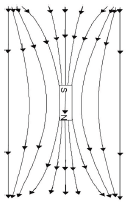 It may surprise you that the magnetic dip affects the compass—it certainly surprised me. After all, it would seem that only the horizontal component would have an effect on a horizontal compass. But in fact the dip θ is used with the horizontal component H to derive the vertical component H tan(θ) which does have an effect on the induced horizontal magnetic field of the ship. The vertical component of the Earth’s magnetic field bends in the presence of soft iron as shown in the figure to the left. Another way to look at this is that the net field is the superposition (the vector sum) of the vertical magnetic field and the dipole magnet induced in the iron. This creates an induced horizontal component due to the vertical field, and this will affect the compass needle. This is negated somewhat by a vertical Flinder’s bar with its upper end at the level of the needle.
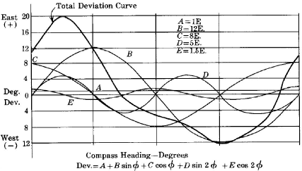
It’s interesting to note that all this was well-known prior to Maxwell’s unification of electromagnetic theory—in fact, he refers to it in his famous treatise. And the basic theory is unchanged from that time; the composite graph shown earlier of the components of magnetic deviation is from the Handbook of Magnetic Compass Adjustment issued by the National Geospatial-Intelligence Agency in 2004.
Other Sources of Magnetic Deviation
There is another effect not taken into account in this chart, the distortion due to heeling of the ship, i.e., the leaning of the ship from wind as well as the transient rolling of the ship. Smith derived equations for all that as well in his manual [Gray presents a nice summary of it all]. Heeling produces a maximum deviation when the ship is heading north or south, and no deviation when heading east or west (although the needle will have less directive force to north in this case). The complementary pitching action of the ship, being more transient that heeling, does not produce a significant difference in deviation on average. Another transient effect found in practice, the Gaussin error (not Gaussian error), is a time lag in magnetic change with heading change of about 2 minutes due to opposing magnetic fields in the soft iron created by eddy currents (by Lenz’s Law). Of greater concern is the retentive error, or the tendency to retain residual, subpermanent magnetism in the hard iron that is accumulated as the ship maintains a set course for a long time (say, several days) while being hammered by waves, an effect that can last from hours to more than a day after a heading change. This certainly required some experience and a good bit of art to reckon in the past.
Add to this the changing effects on magnetic deviation from variable quantities of ammunition on board, varying turns on cable reels, attached boats and nearby ships, personal effects such as watches and belt buckles, stowing of the anchor chain, lightning strikes, the heating of smoke stacks and exhaust pipes, and so on. Newer aluminum boats, for example, don’t provide magnetic shielding of sources below deck, and Barber relates that in one new aluminum cutter the compass deviation obediently tracked the generator speed. With all these effects it’s not surprising that at one time a magnetic compass was often placed high on the mizzenmast for a sailor to climb to take readings, a very effective solution in calm seas but a problematic one when a bobbing ship magnified the needle bounce and swing! (The construction of a compass that would minimize needle swing due to the motion of a ship was also a long-running debate, with the version by William Thomson—later Lord Kelvin—in his popular commercial binnacle eventually losing out to liquid-filled models.)
The direction of permanent magnetism of hard iron is related to the direction that the ship was facing when it was built; the compass needle will be attracted to the part of the ship that was south of it during construction. Smith held that an iron ship should be built with its head in a north-south direction, and preferably south. The effect is due to the alignment of magnetic domains in the iron with the external magnetic field of the Earth while being worked and pounded. In fact, Gilbert had created magnets by hammering iron rods laid in a north-south direction as part of his demonstration that the Earth acts as a mostly dipole magnet. But this initial permanent magnetism doesn’t last, and in some cases over half of a ship’s original permanent magnetism is lost in the course of its first year of use. And while the permanent magnetism of a ship is fairly constant after that point, any collision or repair of the ship will alter that permanent magnetism, requiring a new set of measurements and corrections to be applied.
Ascertaining Ship Parameters
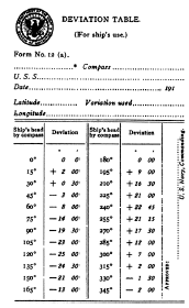
 The measurement of the magnetic deviation parameters for each compass location on a given ship was a tedious job that prompted many proposals for the best method. In general the dip θ at the measurement location was found on shore with a dipping needle. The horizontal component of the Earth’s magnetic field (H) was also found at that location, normalized to 1.0 for a standard location (Greenwich, for Smith). Then the combined horizontal magnetic force of the Earth and ship (H’) was found at each compass location on the ship itself. To do this, the needle of a precision compass was manually rotated to one side and released, and the time for a set number of vibrations was recorded, both on board (T′) and on shore (T). Then H′ / H = T2 / T′2. Measurements were obtained as the ship was swung to different rhumbs of the compass rose, 8 directions for inexact values and 32 for more exact results, executed slowly and in opposite directions to reduce the Gaussin error. The difference between the compass course and the known magnetic heading, or the deviation δ, was also recorded at each rhumb. With varying levels of complexity, the required constants were extracted. For example, the mean directive force to magnetic north λH is found as the average value of H′ cos δ.
For a sub-optimal suite of only 8 measured deviations at 45° intervals (i.e, N, NE, E, SE, S, SW, W and NW), we can find the inexact coefficients from these rules:
A is the mean of the algebraic sum of all the deviations
B is the mean of deviation at E and the negative of the deviation at W
C is the mean of the deviation at N and the negative of the deviation at S
D is the mean of the deviations at NE and SW and the negatives of the deviations at SE and NW
E is the mean of the deviations at N and S and the negatives of the deviations at E and W
 For any more than 8 rhumbs the derivation of the parameters is very complicated and involves solving a complex system of equations developed by Archibald Smith and others. Smith’s equation in A, B, C, D and E is actually a truncation at 2ξ’ of a Fourier series expansion in sines and cosines of multiples of the course ξ′, so these values are the corresponding Fourier coefficients—in fact, the first use of the phrase harmonic analysis is found in William Thomson’s obituary of Archibald Smith [Grattan-Guinness]. For more detailed information on deriving the ship’s parameters in this way, or for deriving the exact coefficients A, B, C, D and E, please see Smith’s Admiralty Manual for the Deviations of the Compass or The Magnetism of Ships and the Deviations of the Compass, Comprising the Three Reports of the Liverpool Compass Commission.
Compensating for the Magnetic Deviation
The magnetic deviation of a ship is typically corrected, even today, by components located in the binnacle holding the compass. Permanent magnets are positioned to compensate for the permanent magnetism of the ship. A vertical soft iron bar (the Flinders bar) is also located near the compass to counter the effects of the vertical component of the Earth’s magnetic field. These correct for the semicircular forces. Soft iron spheres on a rotating base serve to correct for the quadrantal forces, but their positions have to adjusted for the magnetic latitude.
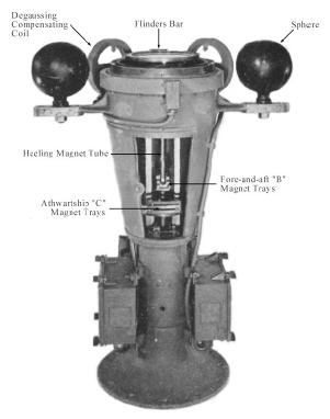 The spheres also help negate magnetic deviations from heeling of the ship. There are also adjustable permanent magnets included to overcome these heeling effects. A permanent magnet mounted vertically directly beneath the compass does not have any effect when the ship is upright, but will correct for heeling error as the compass needle dips a bit in the lean. These permanent magnets also need to be adjusted with latitude.
Finally, there are current-carrying coils in the binnacle that are energized to counter the effects when the ship activates its degaussing coils to elude mines that trigger on the magnetic fields of passing ships.
Occasionally the net effect of magnetic deviation on an uncompensated compass completely negates the magnetic effect from the Earth, and the compass has no preferential direction at all, or only a weak one that makes observations uncertain. For this reason compensation is usually preferable to simply adding a correction in degrees from a table or diagram. I might add that Thomson once said that the chances were 50-50 that the navigator would get the sign wrong in calculating a compass correction [Barber]. Also, the equations given earlier assume a magnetic deviation of less than about 20° in order that B and C can be expressed as simple arcsine functions, and so a certain amount of ship correction is generally needed in an iron ship to ensure this.
 For centuries, long compass needles (say, up to 15 inches) were thought better for higher magnetic strength (true enough) and better stability in rough seas (not true at all). But it happens that there are sextantal deviation terms in 3ξ′ for these long compass needles due to their response to the permanent magnet compensators, and octantal terms in 4ξ′ due to the interaction of these needles with their magnetic images in soft iron compensators. Smith early on had developed a rule for compass card needles, that when there are two needles they should be placed with their ends on the card at 30° to each side of the ends of the north-south diameter of the compass (the lubber line), and when there are four needles they should be placed with their ends at 15° and 45° from the ends of the diameter (30° apart). In this way there are equal moments of inertia parallel and perpendicular to the compass axis, which eliminates wobbling of the card But twenty years later, in analyzing ship data exhibiting higher-order effects, Evans and Smith discovered that small needles arranged in just the way he had prescribed exhibited less sextantal and octantal deviation than one short needle—and exactly zero mathematically! It was “a happy coincidence” according to Smith, and this justified moving the compensating permanent magnets and soft iron correctors much nearer this type of compass for more accurate elimination of the semicircular and quadrantal deviations [see Lyons for proofs].
Because of the calculations required for tabulating the magnetic deviation for all magnetic or compass courses for a location at sea are time-consuming and error-prone, much work was done to create graphical ways of plotting the values for all courses from a few measurements taken at the location. The result could also be used by navigators to read the magnetic deviation quickly and easily while at sea. These graphical calculators are the subject of Part II of this essay.

Very intriguing! I had absolutely no idea of the intricacies of navigating a vessel on the high seas. I was aware of pounded metal taking on the magnetic pole of the location where the pounding occurred, but for some reason never put the impact of metal warships on pre-GPS navigation. So the question remains, as ordinance is fired during battle, does the captain have to understand the exact amount of cannonballs that were fired in order to re-compensate for the change in metal?
Fascinating.. great job!
Thanks! I had no idea either, and I only entered this realm while searching for the source of formulas for magnetic deviation on Lallemand’s hexagonal chart for another essay I’m writing—stumbling across dygograms was an unexpected bonus.
In the case of a wooden ship, differing numbers of cannonballs would cause a definite change in the magnetic deviation, particularly for any compass located near the cannonballs. At the time of these wooden ships most compasses were of fairly shoddy construction anyway, according to Gurney’s book. Nonetheless, it was found very early on that the armory and any metal stores had to be kept away from the compasses, so this effect must have been quite noticeable. Once ships with iron decks appeared, any ammunition below deck would be somewhat shielded by the deck.
I might mention that compasses for submarines were a real problem! Early submarines mounted the compass outside the sub and used sighting tubes to see the needle, but even then the presence of the hull would have had to be greatly compensated. The problem was essentially solved by the invention of the gyrocompass, which maintains a direction in space by its angular momentum rather than by a magnetic force. The development of these was largely driven by their need in submarines. — Ron
LikeLike
About Halley’s magnetic surveys in the North and South Atlantic. He did not determine longitude at sea from Jupiter satellites. That is possible only with high-magnification telescopes which are unusable at sea due to vessel’s motion.
Halley’s method was to estimate time from Lunar appulses, near-conjunctions of the Moon with a star, as it was passed by the midline bisector of the Moon. That was possible only for an astronomer such as Halley, very familiar with stars around the ecliptic; not for an ordinary mariner. It was the first successful measurement of longitude at sea by astronomical means. Halley also stated that he had taken Newton’s reflecting quadrant to sea. See “Astronomical Minds”, by Ted Gerrard, Samos Books, 2007.
Very interesting, thanks! I’ll go back and find where I saw references to Halley using eclipses of Jupiter’s satellites. I’ve also ordered the book you mention from Amazon. It looks fascinating (there is a sample PDF not on Amazon but at the Samos Books site at http://www.samosbooks.org/Astronomical_minds.pdf). At one point in the sample it says that Halley tried to sight Jupiter’s satellites on Fernando de Noronha but could not, and instead relied on a lunar method as you say. After I get the book I’ll update the essay according to the details in the rest of the book. Thank you very much, George! — Ron
LikeLike
For just plain fun with magnets, there’s a series of articles on http://www.evilmadscientist.com that shows how much easier it is to use with modern powerful magnets. Here’s they’re simplest design:
http://www.evilmadscientist.com/article.php/EasyCompass
While it took those mariners a while to realize that iron aboard the ship could affect the direction, with these materials a floating magnet will ignore north and head straight toward any nearby magnetic metal, quickly!
Little mathematics, I’m afraid, but neat to read about.
Thanks, a nice article. After reading it, I now have a new appreciation for the risks of placing a powerful magnet anywhere near a knife, too! — Ron
LikeLike
Hi
Could you please help me. I’m busy installing a wireless weather station and I need to point the wind sensor to true north. I have a compass (360° being magnetic north), but how many degrees left or right of magnetic north is True North?
I am in Nelspruit, 25° 30’01. 73” S and 30° 59’32. 10” E . Elevation – 804m
Thanking you
Thomas Barry
There is a good website to find the magnetic variation (sometimes called magnetic deviation as in this website) for any location in the world:
http://magnetic-declination.com/
If you select South Africa as the country and enter Nelspruit as the city, you get a display where the magnetic declination is given as 18 degrees 5 minutes West. There is a link at the top right of this page called “What is Magnetic Declination?” and if you click on it you arrive at this webpage:
http://magnetic-declination.com/what-is-magnetic-declination.php
This is very useful because it shows you what direction the correction is for the “West” declination. Here we find that true North is 18 degrees 5 minutes (or 18.08 degrees) clockwise (or right) from the magnetic North that is shown on your compass.
LikeLike
Congratulations! I set the compass here in Brazil. He knew the equations, but had no knowledge of the authors. Enjoyed reading the contributions of Matthew Flinders; Archibald Smith, Edmund Halley, but I wonder also about the contribution of Peter Barlow compensation for the compass of ships. Thank you!
Hi Jose. You’re right, Peter Barlow was not discussed, but he did perform important experiments on terrestrial magnetism, including the use of spherical balls to provide magnetic compensation for compasses. Here is a link to his book from 1824 describing his work, which is quite impressive mathematically: http://archive.org/details/essayonmagnetica00barliala The work of Mr. Barlow should have been included in the essay, as he was an important figure. If I have the time to update the essay, I will certainly correct that omission. Thank you for taking the time to comment here—these kinds of contributions from informed readers are what I enjoy most about the blog! — Ron
LikeLike
how do elevation effect on magnetic declination angle?
please formula
Hi Reza. Thanks for your question. I have not seen a formula for the effect of elevation on magnetic declination angle. I would assume it would be very small for any ground location compared to any local effects from minerals in a mountain or such, since the earth is so huge compared to elevation differences on its surface. — Ron
LikeLike
If I understand correctly only a magnet will be pulled or pushed or turned by a magnetic field, and a compass needle needs to be magnetised in order to align itself with the earths magnetic field. Although the earth’s magnetic field will induce magnetism in an un-magnetised needle, this effect is presumably too weak to cause the needle to line up with earth’s the field. Likewise a piece of un-magnetised iron will only be noticeably affected by a permanent magnet when the magnet is close enough to the iron to induce enough magnetism that the iron becomes a temporary magnet and responds to the field of the magnet. Have I got this right?
Right, that sounds like an excellent summary of what’s going on! The surprising thing to me is how much of an effect the relatively weak magnetic field of the earth has on a large enough piece of iron. Please feel free to continue this discussion. — Ron
LikeLike